|
Field test of the ground penetrating radar (GPR)
above karst of Planina cave (Slovenia) for > 150 m depth
Pavel Kalenda, Rudolf Tengler, Stanka Šebela,
Matej Blatnik, Franjo Drole
Abstract
We made a field test of the penetration depth in karst above Planina cave (Slovenia) using a new model of ground penetration radar “Roteg” with maximum power of 5 kV on antenna and 25 MHz medium frequency. We correlated the radargrams with the known Pivka passage of Planina cave, which is 125 – 210 m below the surface. Water-filled cave passages were clearly detectable. The dry passages were detectable too, but the relative amplitudes of reflections were several times smaller than in the case of water-filled passages. New unknown cave passages were detected too. The character of passages (wet/dry) was distinguished with this method according to phase sequence of reflections in the case of large cave passages even at depths > 150 m.
The positive results of this field test are promising not only for speleologists, but for road or building constructors in karst areas as well.
Key words: ground penetrating radar (GPR), karst, georadar “Roteg”
Introduction
The ground penetrating radar (GPR) has become one of the most used devices to search inhomogeneities in the ground to a depth of several meters for its high efficiency work in the field (Karous and Gürtler 1997, Bláha et al., 1999). GPR is based on the transmission of high frequency pulses (usually 25 to 1000 MHz) by one antenna and by receiving the reflections of those pulses by second antenna. A delay of the reflections is proportional to the depth of the interface of materials with different conductivity (σ), which reflects the pulses. The amplitude of reflections is proportional to the ratio of electric conductivity of these materials (σ) and decreases exponentially with depth, depending on the environmental permittivity (ε) (van der Kruk, et al.1999).
For commonly used GPR and typical environments in Central Europe with hundreds Ωm resistivity, the penetration depth can be of a few meters up to several ten meters (Bláha et al. 1999; Chamberlain et al. 2000). During the measurement on glaciers, the reflections were detected from depths of hundreds of meters to first kilometers (Arcone, 2009). Smith and Jol (1995) experimentally estimated that the penetration depth for 25 MHz antenna and Quaternary sedimentary environment (above the surface of mineralized water) is between 52 and 57 meters. For 100 MHz antenna the penetration depth was reduced to 37 m. The results of experimental measurements above the cave Divaška jama (Gosar 2012) corresponds with such estimations. In this case it was able to detect the reflections from the ceiling of the cave from depths of up to 30 m using special antennas with a length of 9.25 m and a center frequency of 50 MHz in typical karst environment. Reflections from the ceiling of a cave at a depth of about 40 m were not revealed by this method.
We tested the penetration depth of new model of GPR “Roteg” (manufactured by private firm RTG-Tengler) in speleological known karst areas in the Czech Republic in 2015 (Tengler et al. 2016). The results were promising and we recognized the reflections from caves at a depth of 100 m below the surface. Because these results gave hope that in karst areas it is possible to detect reflections from caves and cavities from depths exceeding 100 m, we have chosen Postojna Cave system and Planina cave in particular as a test site (Fig.2).
Area under study
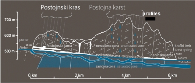 Fig. 1 Fig. 1
Karst between Postojna and Planina builds up about 800 m thick limestones and dolomites of Cretaceous age (see Fig.1). Carbonate beds of various thicknesses are overthrusted folded and faulted due to regional tectonics. Important structural elements of folding are Postojna anticline and Studeno syncline, which are oriented in SE–NW direction. Significant faults are in Dinaric direction (SE–NW; dextral strike-slip fault) and in Cross-Dinaric direction (sinistral strike-slip fault); some of them are vertical (Hajna 2015).
Methods
The new GPR, compared to existing GPR, is characterized by much higher pulse power (up to 5 MW – at a pulse length of 1 s), higher voltage of antennas (5-15 kV) and in particular the special design of the pulse generator, which bypasses commonly used semiconductor components MOS and LDMOS and uses a spark gap. This spark gap (discharger) produces Dirac pulses of lengths of up to 3 ns by directly discharging capacitors (RTG-Tengler 2013). The predominant frequencies are selected from continuous spectrum by the special antenna, which is tuned to them. The 6-meter antenna is tuned to predominant frequency of 25 MHz, 3-meter antenna is tuned to 50 MHz and 1-meter antenna is tuned to 150 MHz. In optimal conditions, when the soil and young sedimentary cover is not thicker more than a few meters, the reflections of cave ceiling were clearly detectable using the 6-meter antennas at depths of around 100 meters under the karst surface (Tengler et al. 2016).
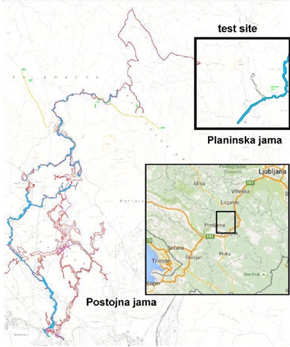 Fig. 2 Fig. 2
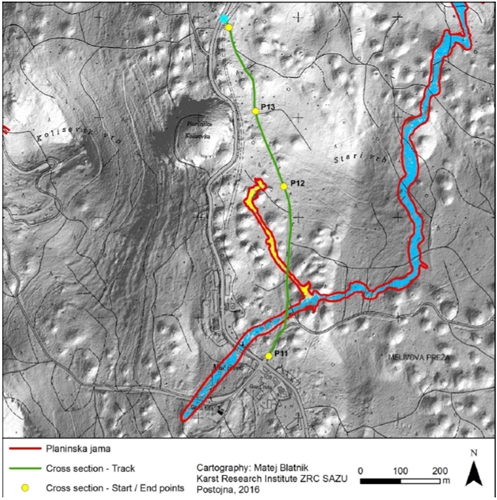 Fig. 3 Fig. 3
GPR produces the short electromagnetic pulses, which are transmitted to the ground by transmitting antenna. The second antenna of the GPR measures the travel time and amplitude of the reflected electromagnetic waves, which are reflected on inhomogeneities (from the viewpoint of electrical conductivity). The delay of the receiving signal depends on the depth of inhomogeneity and velocity of electromagnetic signals in the rock. The velocity of EM signal in rock-mass depends on its permittivity (ε) according to the equation (Allred et al. 2008):
vm=v0/sqrt(εm/ ε0), where:
vm – velocity of the wave propagation through any material
v0 – speed of light in air
εm – permittivity of the material
ε0 – permittivity of free space or vakuum.
In our case we used the velocity for wet limestone 0.12 m/ns (Cassidy, 2009).
The range resolution r between two inhomogeneities depends on the length of the pulse and the velocity of electromagnetic signal in rocks according to the equation (Annan, 2009)
r = vm .W/4, where
W is pulse width.
In our case, the lengths of the pulses are shorter than 3 ns and therefore the radial resolution should be better than 1 m independently on the depth (distance from GPR). We can estimate the range resolution directly from medium wavelength. For 25 MHz antenna, it will be 40 ns * 0.12 m/ns/ 4 = 1.2 m.
The lateral resolution L between two inhomogeneities depends on the length of the pulse and the velocity of electromagnetic signal in rocks according to the equation
L = sqrt(vm .W.d/2), where
d is the distance from the GPR.
In our case the lateral resolution in the depth of 100 m should be better than 16 m.
The penetration depth is the crucial factor, which limits the applications of GPRs. For high-frequency GPRs, the relatively small penetration depth (only several meters) is due to high attenuation of the high-frequency signal. The penetration depth for low-frequency GPR (below 100 MHz) is limited to dozen of meters mostly by mineralized water, which converts the energy to the heat (Smith 1995, van der Kruk et al. 1999).
Preliminary test in Moravian Karst (Czech Republic) confirms that in suitable conditions (limestone covered by one meter thick soil), the penetration depth is larger than 100 m and in the case of high thickness of wet soil, the penetration depth decreased to 40 m (Tengler et al. 2016).
Data acquisition
Field measurements were done on the unpaved forest road at the highest elevations of the limestone plateau between Postojna and Planina settlements (620-643 m a.s.l.). The track is crossing the known passage of Planina Cave filled with water (about 450 m a.s.l.) and a dry branch of the same cave (Fig.3). Both parts of the cave are located about 170-190 meters below the surface.
We started the measurement on the test site on April 19, 2016 in the afternoon after a short and small rain (2 hours long). The conditions were typical for spring – the karst massif was almost saturated by water after the winter snowmelt and spring rain. The river Pivka level was higher than average.
The total length of the entire profile (p11, p12 and p13) on the forest road was 855 m (405 m + 240 m + 210 m). The antennas were laterally separated from each other by 3 up to 6 m according the width of the forest road (see Fig. 4). Sometimes, the distance between antennas was only 3 m and therefore the measured signal to the depth of 30 up to 50 m was in its limitation (saturated, over gained).
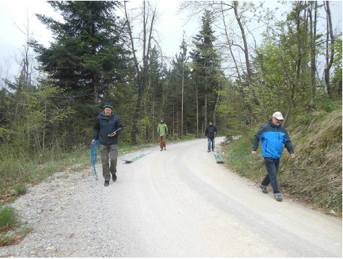 Fig. 4 Fig. 4
For measurements we used 6 m long antennas (Fig. 4) with medium frequency of 25 MHz. We summarized 20 pulses at a speed of the measurement of about 4 km/h. Step between measurements was 0.1 m, GPS accuracy was about 1 m. Length of each record was 16,387 samples and step 0.277 ns (all together 4540 ns,). The sampling frequency was 3.6 GHz. The filtered radargrams are presented on Figs 5 and 6.
Results and discussion
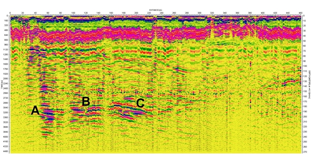 Fig. 5 Fig. 5
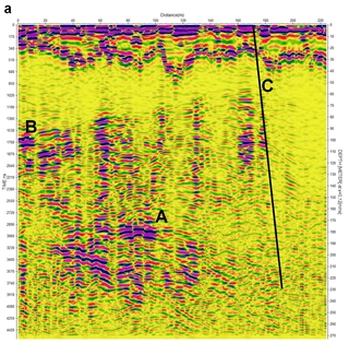 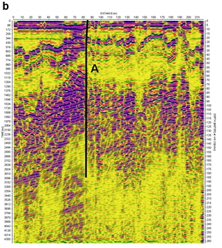
Fig. 6
The amplitudes of reflected waves to a depth of about 30-50 meters (500-750 ns) were over the measuring range at all profiles. Therefore, any hints of reflections from these depths are irrelevant. It was due to the measurement was set to obtain the high quality reflections from depths exceeding 100 m, this aim was realized and is discussed.
On the profile p11 there is a distinct group of reflexes between the horizontal positions 30 and 90 m at a depth from 60 to 100 m (Fig. 5). This group of reflexes is followed by continually inclined reflective interface up to the horizontal position of 230 m and a depth of 110 m. It can be a significant layer filled with a conductive material (for example detritus or wet mélange) or a fracture with small inclination. There are clear reflections in the horizontal positions/depths of 50m / 175 – 180 m (A), 90 m / 180 m (B) and between 140 m and 170 m / 180 – 190 m (C). In the case C, the character of reflections rather points to the sloping reflective interface between water and limestone rather than hyperbolic continuation of reflection from linear anomalies..
In comparison with the map of Planina cave, we can conclude that the most significant reflexes at the horizontal positions from 50 to 170 meters correspond to water environment according to their depth and amplitude of reflections . The part of the known cave in this area is completely filled with water (Fig. 7). As well as the large amplitude of the reflected signal, the sequence of polarity red – blue – red corresponds with the high conductivity of mineralized water. If the air is present between water and cave ceiling, then it is under the vertical resolution of the geo-radar (with the full range of frequencies). And vice versa, the sequence of signal polarities blue – red – blue indicates the anomalously low conductivity or dielectric constant, which corresponds in karst areas most frequently with air filled passages. These, presumably dry cave passages are marked in Figure 7 by green ellipses.
The reflective interface at the horizontal position of 210-250 m corresponds to dry cave passages, which continue away from the water passage toward the NWN, according to their depth, smaller amplitude and sequence of signal polarity.
The strongest group of reflexes on profile p12 is between the horizontal positions 70 m and 100 m at a depth of 175 m (A) (Fig. 6). It is interesting how the polarity of the signal is changing at the course of about 30 m length, suggesting a change in the character of fillings in the cave. Comparing with the map of Planina cave, we can see that this anomaly is located in the continuation of the dry part of the cave, which is not far from the profile (60 meters) and which terminates by collapse of the cave. Tectonics in the area under study also points to a continuation of the corridor to ESE, towards under the test profile. The depth of reflections corresponds to the depth of the cave.
Other two important reflexes, probably from the unknown caves, are clearly recognizable at the horizontal positions of 10 m (B) and 175 m (C), both approximately at the same depth of about 100 m. Comparing with the profile p11, it seems that possible unknown cave level was developed at this depth. This can be related to Planinska Koliševka collapse doline, which bottom is located at an elevation of 557 m a.s.l. (about 40 m below the profiles).
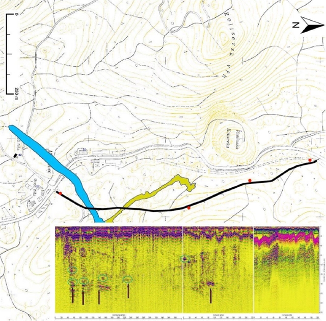 Fig. 7 Fig. 7
On the profile p13, the anomalous reflections probably from tectonic structure are seen at horizontal position of about 80 m and depth of 30 m and 60 m (A) (Fig. 6b). The collapse doline Planinska Koliševka is probably developed at the same tectonics (Fig. 7). In addition to small caves, developed on this tectonics, we could not see any significant reflexes at a depth of about 180 m. The reflections from individual layers and sequence of layers of different resistances are well observable here. The change in the nature of limestone northerly of tectonics (at the positions of 180 m at the profile p12) is noticeable. The northern part of area under study exhibits more pronounced layering of limestone than limestone in the south.
Conclusion
The new model of GPR “Roteg” with 6-m long antennas and 25 MHz medium frequency was able to detect the reflections from water-filled Planina cave from the depth of about 180 m. Additionally, the clearly recognized reflections were seen from the depth of about 240 m (in the phreatic zone). The dry passages of Planina cave were detectable from the depth of 170 m below the surface, although their relative amplitude was several times less, than it was in the case of water-filled passages at the same depth. Moreover, we were able to distinguish the fillings of the passages according to the polarity of amplitudes and/or relative amplitude of reflections.
We were able to recognize the positions of tectonic structures in the area according to reflections of the fault plane and/or according to changes of the behavior of karst massif (reflections / no reflections of layers).
We have found several dry and water-filled cave passages in the area, which were not known before, especially at depths of 60 – 100 m below the surface, which could be the relict of the older cave system.
The results of the measurement confirmed the previous results from Moravian Karst (Czech Republic) that the penetration depth in the optimal conditions (limestone area, small thickness of soil, caves filled with water), using the longer antennas (6 m) and maximal power of 5 kV, could reach 200 m. This is good news not only for speleologists, but also for building and road constructors anywhere in the karst areas.
References
Allred B.J., Daniels J.J., Ehsani M.R. (2008): Handbook of Agricultural Geophysics. CRC Press Taylor Francis Group, Boca Raton.
Annan, A. P. (2009): Ground Penetrating Radar: Theory and Applications [online]. Edited by Harry M. Jol . Amsterdam : Elsevier, 2009 [cit. 2011-05-05]. Electromagnetic Principles of Ground Penetrating Radar, s. 1-40. http://www.sciencedirect.com/science/article/B8MD5-4VCY128-2/2/128792940ae4396694f3d11cccac0984
Arcone, S. A. (2009): Ground Penetrating Radar: Theory and Applications [online]. Edited by Harry M. Jol . Amsterdam : Elsevier, 2009 [cit. 2011-05-05]. Glaciers And Ice Sheets, s. 361-392. http://www.sciencedirect.com/science/article/pii/B9780444533487000120
Bláha, P., Karous, M., Kněz, J., Müller, K. (1999): Možnosti georadaru v inženýrském průzkumu. Geotechnika. 1999, Vol. 2, No. 3, 12-15.
Cassidy, N. J. (2009): Ground Penetrating Radar: Theory and Applications [online]. Edited by Harry M. Jol . Amsterdam : Elsevier, 2009 [cit. 2011-05-05]. Electrical and Magnetic Properties od Rocks, Soils and Fluids, s. 41-72.
Chamberlain, A.T., Sellers, W., Proctor, C., and Coard, R. (2000): Cave detection in limestone using ground penetrating radar: Journal of Archaeological Science, v. 27, p. 957–964. doi:10.1006/jasc.1999.0525.
Gosar, A. (2012): Analysis of the capabilities of low frequency ground penetrating radar for cavities detection in rough terrain conditions: The case of Divača cave, Slovenia. Acta Carsologica, 41/1, 77-88, Postojna.
Gosar A. & Čeru T. (2016): Search for an artificially buried karst cave entrance using ground penetrating radar: a successful case of locating the S-19 Cave in the Mt. Kanin massif (NW Slovenia). International Journal of Speleology (Edizione Italiana) 45(2):135-147.
Hajna, N.Z. (2015): Postojnska jama. Excursion 4, Friday, June 19th 2015. In: 23-th International Karstological School “Classical Karst”, Postojna, June 15 to 21, 2015. 50-58.
Karous, M., Gürtler, R. (1997): Použití georadaru při mělkém geotechnickém průzkumu. NO DIG, Zpravodaj Č.spol. pro bezvýk. techn., roč. 3, č.2, 14-20, Praha.
RTG-Tengler (2013): http://georadar.rtg-tengler.cz/geologicky-zlom-u-sobotky
Smith, D. G. and Jol, H. M. (1995): Ground penetrating radar: antenna frequencies and maximum probable depths of penetration in Quaternary sediments. Journal of Applied Geophysics. January 1995, Vol. 33, Issues 1-3, s. 93-100. http://www.sciencedirect.com/science/article/pii/0926985195900322
Tengler, R., Kalenda, P., Doležal, F.K., Chlup, L. (2016): Testování nového typu georadaru s velkým hloubkovým dosahem, Speleofórum 2016, Vol. 35, 35-42.
van der Kruk J., Slob E.C., Fokkema J.T. (1999): Background of ground-penetrating radar measurements. Geologie en Mijnbouw, 77: 177–188.
|